DBD2 - DCC Block Detector Application Information
Detector for SIC24:
The DBD2 can be used as a block occupancy detector for the SIC24. The DBD2 can operate from 5 volts which the SIC24 provides on it's input connectors. The DBD2 output voltage levels are then compatible with the SIC24 inputs. See SIC24 application information for a diagram of two DBD2s connected to a SIC24.
Sensitivity Issues:
There are several reasons why the DBD2 may indicate a block is occupied when in fact there is no engine or rolling stock in the block. If there is a LED or some kind of indicator that is powered from the track, this could cause the DBD2 to show occupied. High humidity conditions can cause a problem. Perhaps the ballast is damp for some reason. Water can act like a resistor between the rails. There can be enough distributed capacitance in the DCC wires to cause a small amount of current to flow and thus causing a false indication. To keep the capacitance to a minimum, place the DBD2 close to the block it is detecting. Keep the the block feed wire or any of the block track feeder wires from running right next to other wires for long distances. Do not twist the block feed wire with another wire.
In some cases it may be desirable to decrease the sensitivity of the DBD2. This picture shows where to solder resistors to decrease the sensitivity. A 2.2K resistor will give about a 20 ma trigger current. A 1K resistor will give about a 75 ma trigger current. If possible use a 1/4 watt resistor. Also, keep the resistor leads short.
You can use the DBD2 for over current warning by connecting a buzzer to one of its outputs. Using a resistor in the 22 to 27 ohm range will cause the DBD2 to trigger in the 2 to 3 amp area. Experimentation will give you the exact trigger point desired.
Remote LED Indication:
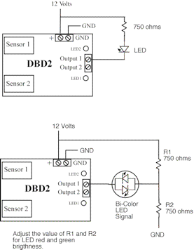
The DBD2 can be used to drive a remote LED to show block occupancy status. The first diagram shows the DBD2 driving a remote LED. When the block becomes occupied the DBD2 turns on the LED.
The next diagram shows the DBD2 controlling a two lead bi-color LED. When the block is unoccupied the LED is green. When the block is occupied the LED is red.
In each diagram only output 1 of the DBD2 is shown connected. Output 2 could be connected in any of the ways as output 1.
When driving a LED a resistor is required to limit the current in the LED.

