SHD2 and JMRI Application Information
Setting up JMRI for SHD2 :
There are several ways signals can be implemented in JMRI. For the SHD2 using signal heads and masts with signal mast logic works well. Each signal head requires an address. Start by adding heads to the signal heads table. SHD2 is a DCC signal decoder and can control 2 heads.
Example of SHD2 addressing. The SHD2 is programmed with the address desired for the its first head (23). The address of the SHD2 second head will be the address of 23 plus 1 = 24.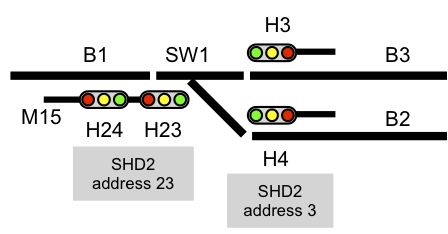
NOTE: Knowledge of JMRI is required. This just shows how to create a mast (M15) with two heads. This does not enter into setting up JMRI signal logic.
JMRI includes several programs. Open PanelPro. Then from the main menu select Tools.
Open the Signal Heads table to add a head.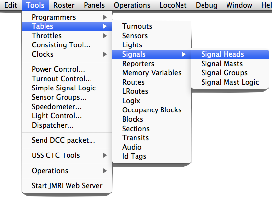
Signal Heads Table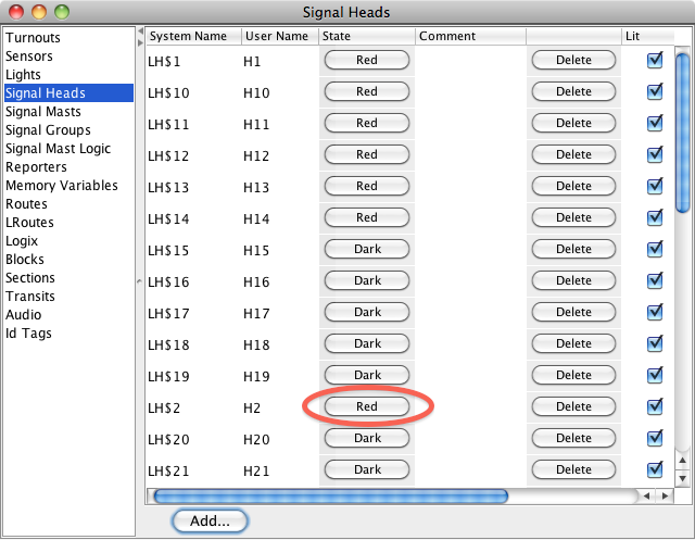
Add a head. Select DCC Signal Decoder. Select the System that is being used. The example shows LocoNet. Enter a head address. Each SHD2 has two addresses. One of the SHD2 addresses must match this address for the head to be controlled. A user name is helpful when defining masts. Use default aspect numbering. The system name shown in the Signal Heads Table will automatically be assigned based of the system you select.
Note: NCE PowerPro or PowerCab with USB adaptor - The lowest address the first signal head can have is 5 – therefore you will need to change the factory default SHD2 address from 1 to 5 or greater. Set the JMRI DCC Signal Decoder Hardware Address to the same as the SHD2 and do not check the Offset Address box. This was tested with JMRI 4.0.
If you have a SHD2(s) connected to your system you can test the signals by setting a signal head aspect. Use the Signal Heads Table and click on an aspect button in that State column. See high light above for H2 in the Signal Heads Table.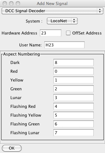
Open the Signal Masts table and add a mast. A double head mast requires 2 heads be defined in the signal heads table.
Signal Masts Table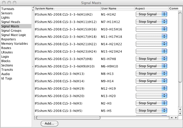
Add a mast. Enter the mast name. Using the head names in the mast name is helpful. The name will be displayed on the panel with a mouse over.
Select the signal system and mast type.
Select mast driver as "Signal Head Controlled Mast".
The system name shown in the Signal Masts Table will automatically be assigned.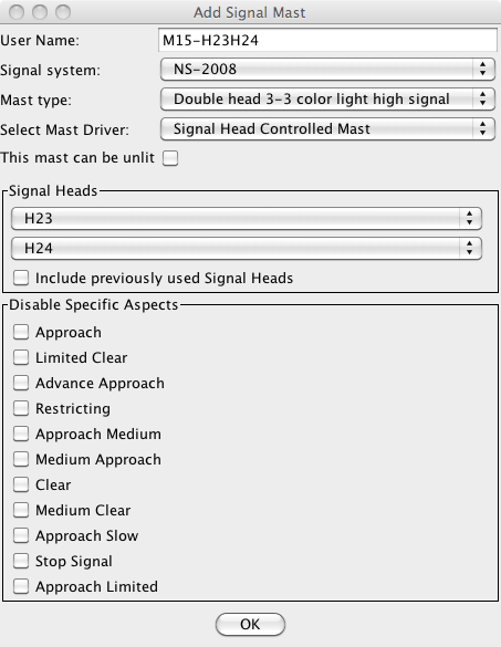
If you have a SHD2(s) connected to your system you can test the signals by setting a signal mast aspect. Use the Signal Masts Table and select an aspect from the pop aspect menu.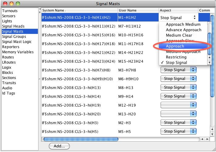
Before setting up JMRI signal mast logic, turnouts and/or blocks must be defined.
