SHD2 and RR&Co Application Information
Setting up SHD2 for control with turnout commands:
Initial production of the SHD2 did not support control with turnout commands. When ordering be sure and specify version 2!
The SHD2 must be configured by programming a turnout (switch) address and setting a configuration option. Once completed the SHD2 will respond to turnout commands for each aspect. Each signal head requires two address numbers to utilize four aspects. Since the SHD2 drives two heads four consecutive address are required. This is the way the Digitrax SE8C works.
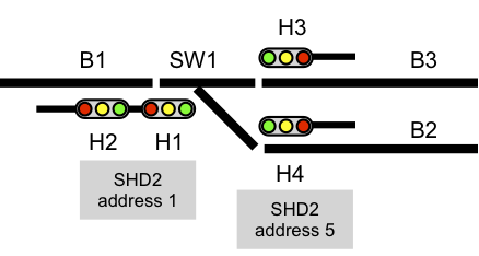
Example of SHD2 addressing: The SHD2 turnout address CVs are programmed with the desired base address for the first head (1). Head 1 will use addresses 1 and 2. Head 2 will use addresses 3 and 4. To program, connect the SHD2 power pins to the programming track and use page mode.
For this example, program CV5 = 1, CV6 = 0 and CV29 = 4. (x = 1)
| Aspect | Address | Address | ||
|---|---|---|---|---|
| Head 1 | Head 2 | |||
| Red | Address x throw | 1 t | Address x+2 throw | 3 t |
| Green | Address x close | 1 c | Address x+2 close | 3 c |
| Yellow | Address x+1 throw | 2 t | Address x+3 throw | 4 t |
| Flashing yellow | Address x+1 close | 2 c | Address x+3 close | 4 c |
Note: Since the actual turnout on the layout may be controlled by turnout commands there can be no over lapping addresses. That is, addresses used for signal control must be different than addresses used for turnouts.
Setting up RR&Co for SHD2 :
NOTE: Knowledge of RR&Co is required. This just shows an overview of how to create a signal head. This does not enter into setting up RR&Co signal logic.
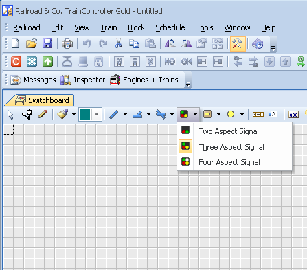
Select a Three Aspect Signal from the menu to add a signal head with red, yellow and green aspects. Flashing yellow is not used with a three aspect head. With three aspects two addresses are still used.
Select the signal icon Properties. Set Address to 1 and Addr. 2 to 2. Set the Output Configuration as shown.
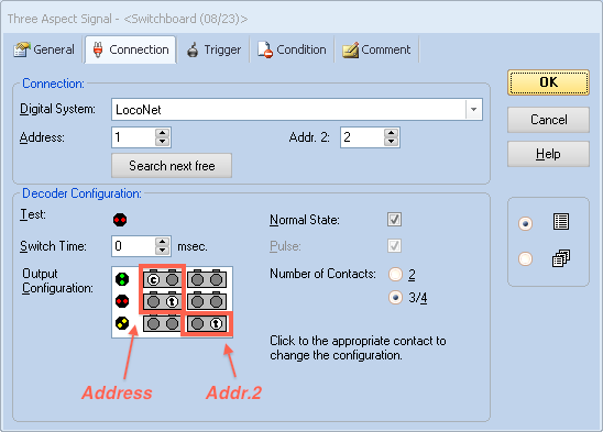
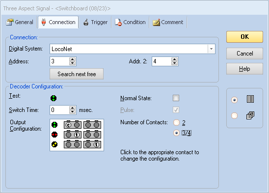
Add another Three Aspect Signal. Select the signal icon Properties. Set Address to 3 and Addr. 2 to 4. Set the Output Configuration as shown.
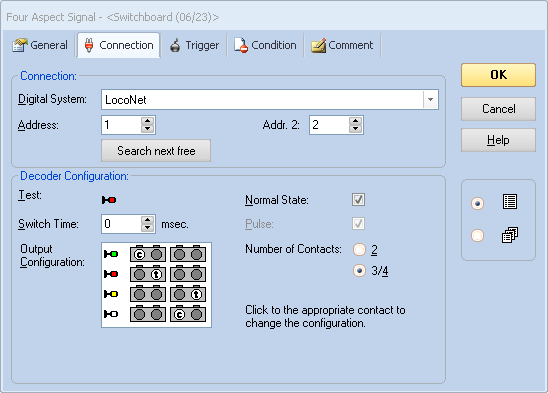
Example of a Four Aspect Signal. Aspects will be red, green, yellow and flashing yellow. With three and four aspects two addresses are used per head.