Using the SRC8 to Indicate a Route
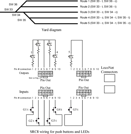
The SRC8 provides a convenient way to control routes. Sometimes it may be important to indicate which route is active. In this example five routes will be defined to access five tracks in a yard ladder.
Each route will be activated by a push button connected to a SRC8 input and the respective output will indicate the active route. The SRC8 address is set so that each route has a pseudo switch (not a physical switch) address as it's execution address. This is also the address the controls the output LEDs. When a button is pressed a route execution switch address is sent. The respective output LED is tuned on and all the switch addresses in the route are sent.
It is important the remember that the LEDs connected to the outputs are being used as route indicators and not real switch state indicators. Since only one route is active at a time then only one LED can be on at a time in this example. Note that a green and red LED could be connected to each group output so that green would show the active route and red show inactive ones. In that case only one green LED would be on at a time. Any given route has to include the real switch addresses and the pseudo addresses. The pseudo addresses are the ones that are used for controlling the output LEDs. Stated another way, each route has to send the real switch addresses and the pseudo switch addresses that will turn off all the other route active LEDs.
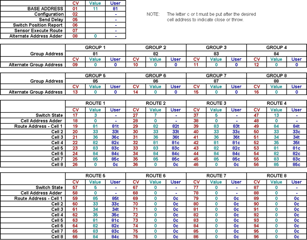
In this example CV1 is programmed with a value of 11. This sets the group address from 81 to 88 which are the pseudo addresses. Only the first five groups are used as there are only five routes. The actual switch addresses are 33 to 36 as depicted in the yard ladder diagram. A wiring diagram of buttons and LEDs is also shown.
When the button connected to input group 1 throw (G1t) is pressed a 81 throw command is issued. Note that the close inputs are not used. When the SRC8 receives this 81 throw it turns on group 1 thrown LED and executes route 1. Route 1 sends switch addresses 33t and 36t and pseudo addresses 82c though 85c. Any other route LED indicator has now been turned off. Notice in the spreadsheet below each route is configured like this with the switch addresses and the pseudo switch addresses.
A template for the SRC8 CV calculator spreadsheet can be downloaded from our Support Tools page.