CSC - Central Signal Controller
Discontinued
The CSC (Central Signal Controller) is uniquely suited to control the SHD2 (dual signal head decoder). It can also control indicators on a layout or a CTC panel such as block occupancy and switch (turnout) position. The CSC has build-in customizable logic to implement various signal schemes. This includes ABS, APB and prototypical grade crossing. It can receive switch command and sensor/block detection messages from the serial bus and/or switch and block state from the inputs. It uses this information to determine signal states with the built-in logic. The number of wires to implement a signal system is greatly reduced when using the CSC and the SHD2.
MSRP - 66.95 USD
Manual in PDF format
Features:
• Built-in logic for automatically controlling signals
• Control up to 10 SHD2 (22 signal heads)
• Configurable to model many signaling systems
• Computer not required for signal control
• Built-in signal configuration options
• 16 outputs for LED indicators and Tortoise™ switch machines for turnout control
• 2 outputs for small servos
• 16 inputs for occupancy sensors (block detectors), turnout state and push buttons
• Serial bus reduces system wiring
• Digitrax LocoNet® compatible
• DCC gateway to serial bus
Features differences from SIC24AD:
• Controls SHD2 dual signal head decoder
• Increased number of logic cells
• 16 input and outputs
• Support for 2 servos
• Ops mode addresses up to 16000
• Support for Digitrax SE8C
• Requires a tool like JMRI DecoderPro for custom programming
Operation:
Typical signal control is based on some set of rules or logic to turn each LED on. Consequently, some logic is required to turn on and off a signal. In order to accomplish this, the CSC has a logic cells that controls signal aspects. The logic is programmable so you can control almost any kind of signals. The CSC uses block addresses, switch (turnout) addresses and DCC signal head addresses (SHD2 addresses) to determine what the signal aspect should be.
If more than one CSC is used in a signal system the serial bus is used to pass information between CSCs. Since communication is done over a serial bus, additional wires to implement a signal system is reduced. The CSC is compatible with LocoNet® block detectors such as the BlocD8 or detectors connected to its inputs such as the DBD22 .
Typically the CSC uses information via it's inputs or via the serial bus to determine the signal state. However, by enabling the DCC gateway the CSC can also receive switch state information from the track DCC. This is very similar to an accessory (stationary) decoder.
Programming:
JMRI DecoderPro is the preferred way to program the CSC in "On the Main" Operations (Ops) mode via the serial bus . The CSC can be very challenging to program because of it's logic capability. To assist in programming, there are several built-in setups. These setups implement various signal schemes. Once a setup is selected, the logic is automatically determined and all the required CVs programmed.
Compatibility:
The CSC is not fully compatible with DCC systems that do not support accessory commands (example - control switches).
Setup Diagrams:
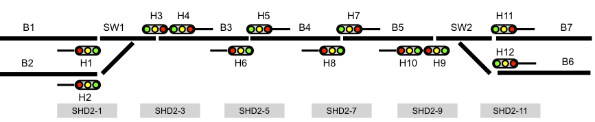
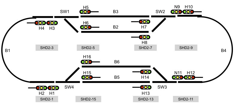
The following diagrams show a couple of the Setups that are built into the CSC. These can be implemented to help you get stated in signaling. JMRI rosters with these setups are available which provide an easy way to make changes. Other setups include four blocks of ABS signals and a grade crossing.
In the diagrams SHD2-x represents a SHD2 driving 2 heads with a related address.
ABS Loop Setup:
Simple APB Setup: